Gooney Bird Drone
  • Home
  • Latest News
  • Specifications
  • Images and Video
  • About/FAQs
  • Media
  • Contact

GB Build Blog

First Flight! (Powered, VTOL)

6/11/2020

1 Comment

 
Picture
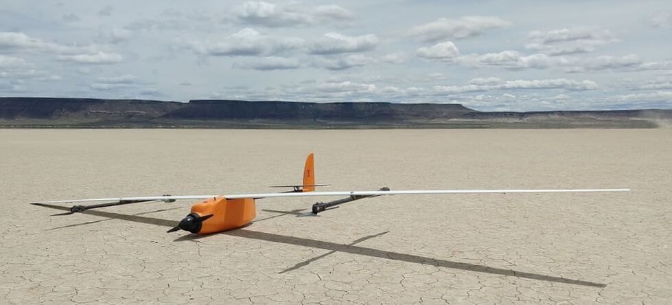
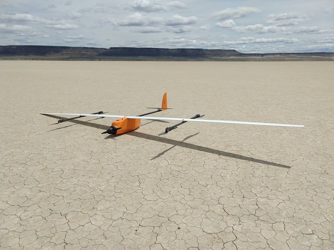
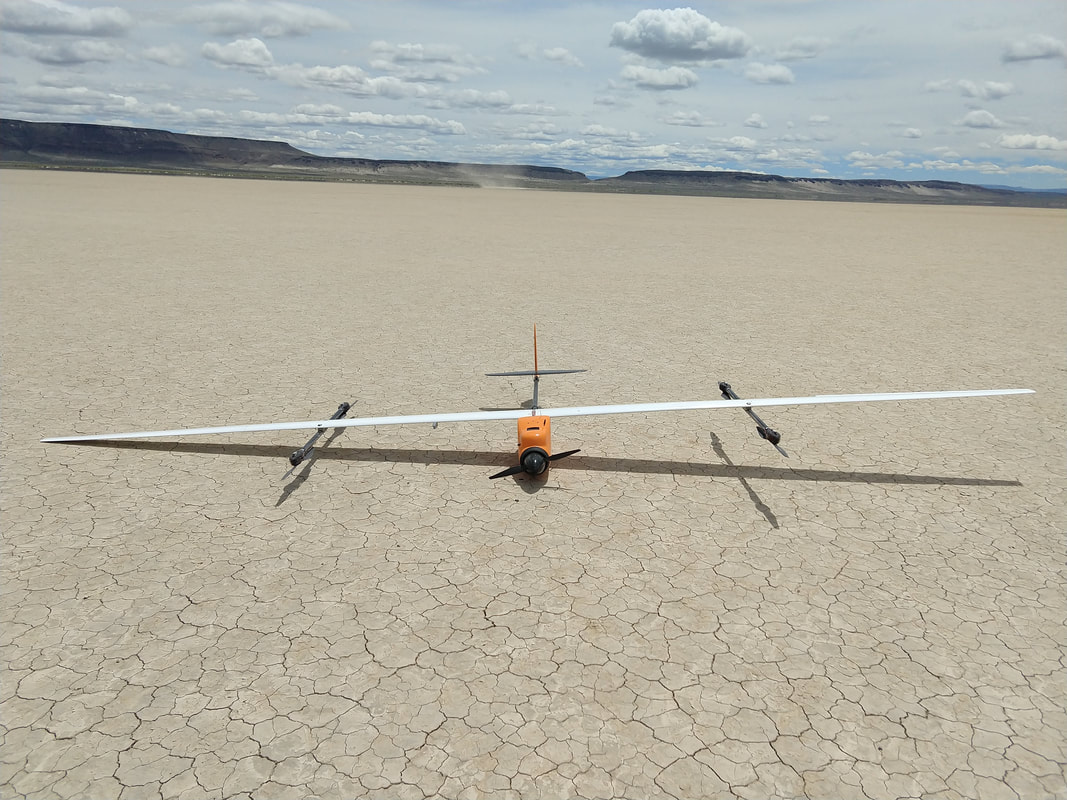
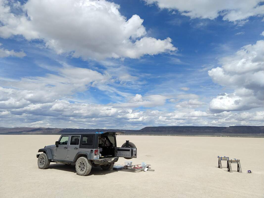
On Monday, June 8, I drove seven hours to the Alvord Desert in SE Oregon. Given that this project has only one airframe that cannot be lost (and no resources to replace it), it was an easy decision to make the trip. After waiting for the wind to calm down, I had a window Tuesday afternoon. There were a few technical issues, but the flight was overall successful and GB was in the air for 1 hour, 6 minutes.

​The flight was terminated early when an air bubble sensor persistently indicated the presence of air in the header tank fuel feeder line and the wind had increased above 15 knots. The fuel load was small, but should have been sufficient for about 10 hours of flight time. Given that the fixed-wing flight control PID loops had been tuned and autonomous flight modes were working well, I decided to quit while still ahead. I drove home Tuesday night/Wednesday morning and started processing the telemetry data on Wednesday evening.
Flight Details:
Takeoff Altitude: 1,224 meters GPS (4,016 feet MSL)
Flight Altitude: 100 meters AGL for most of the flight
Temperature: 27C (80F)
​Density Altitude (TO): ~1,920 meters (6,300 feet)
Takeoff Time: 2:18:45 (PDT)
Landing Time: 3:25:25
Airspeed: ~40 knots true. This is faster than the optimum loiter speed for the fuel load, even at this altitude. It was selected for safety because I had not verified the pitot tube calibration at this altitude.
Weather: Calm at takeoff -- timed between the dust devils moving across the desert. About 30 minutes in, wind increased to a steady 15 knots and eventually hit 20 knots. Aircraft was landed in a lull.
1 Comment

Test Hops

4/10/2020

1 Comment

 
Not too much to report.
  • The stock GF30 fuel pump was working, but it's a bit intricate and fragile so I designed and prototyped a CNC aluminum fuel pump. It is based on the diaphragm membrane from a WYB carburetor. It works!
  • The new engine (GF30 II) has been integrated and is undergoing testing on my test bench.
  • With the stripped down fuselage hard mounted and the engine installed, vibration was fine in the X and Y directions, but a little excessive in Z. I need to test with the full airframe assembled and unconstrained to figure out if this is a real problem or just a result of bad fixturing.
  • I needed to record a quick "win" so I put the wings on and did some more VTOL testing. It was the first time I used altitude hold and there were no problems.
  • Progress is slow as I've only been able to devote about 4 hours a day on the project.
1 Comment

Bogging Down (engine pun intended)

3/17/2020

0 Comments

 
Picture
Internal combustion engines (ICE) are both a blessing and a curse. They are mechanically simple and enable very long flight times. However, the design and tuning of them can sometimes feel like more of an art than a science.

Comparing them with electric motors, even a small carbureted 4-stroke ICE can burn gasoline at a rate equivalent to a specific energy of 2,000 W*hr/kg. For comparison, the better lithium ion cylindrical battery cells can only reach 240 W*hr/kg if used slowly. Not only does the ICE/gasoline have an order of magnitude better specific energy performance, but the vehicle gets lighter as fuel is burned and requires less power to remain airborne whereas a battery-powered vehicle's weight remains constant.

I took apart my first glow 2-stroke engine at age 12, started working on motorcycles at age 16, and rebuilt Stihl chainsaws on rainy weekends as a side-hussle up in Alaska in my early 20's. Based on that, one would think that I love internal combustion engines, but I very much do not. I view them as a necessary evil .. and often times a huge pain in the rear. Even at 1/10 the endurance, the fact that electric propulsion is so simple to implement, operate, and maintain is why it remains a valid design option.

After spending many hours designing, building, and testing the the Honda GX25 engine package for Gooney Bird, I've decided that it remains lacking for this application. It always started and ran dependably and would be adequate to beat the current 32-hour VTOL endurance record -- and do so while operating at 4,000 feet MSL over the Alvord Desert with a 50% fuel load. However, performance would be marginal at that altitude with a 100% fuel load. Rather than make a record flight attempt and then re-engine the vehicle, I've decided to 'bite the bullet' and focus on a more powerful engine for all flights.

I bench tested a 37cc stratified combustion 2-stroke engine. This engine seemed to have good top-end power, but it had poor mixture control. Given the inherently complicated nature of a custom intake manifold for a stratified combustion engine with multiple intakes and throttle valves, I decided not to pursue this path .. at least for now. Perhaps this will be a future science project.

I also tested a more conventional OS GF30 II gasoline 4-stroke engine and am happy with it so far. Work is ongoing but with the higher compression ratio, fuel flows during loiter power levels are looking comparable to the GX25 .. and it has considerably more top-end power. Because the GF30 is a pre-mix engine, I don't have to worry about lubrication while running it at low revs. I was always worried about operating the GX25 at under 3,500 RPM for extended periods as it has a wet sump/slinger type lubrication system.

​Pictures from the past 10 days are below.
​
Picture
The OS GF30 II engine arrived March 6th. Within 24 hours I had designed, printed, installed, and started running with two different 3D printed nylon intake manifolds. Nylon has both chemical resistance and heat resistance but you need an all-metal print head to make parts with an FDM printer. It is shown running with a Walbro WYB carburettor.
Picture
Here is the GF30 engine with a carburetor from a small glow 2-stroke. It doesn't have a built-in fuel pump, but it does have a very small throat which is desirable for this application. I'm leaning towards flying with the WYB carb, but this one is working surprisingly well.
Picture
A friend was curious about the amount of valve lift overlap in the GF30. To measure this, all you need is a dial indicator, ignition timing wheel, and a piece of scrap wire.
Picture
Picture
Here is a screen grab of the SolidWorks CAD model of the new GF30 engine shroud and mount. It took about 20 hours of design time and the full set of parts is currently being 3D printed by a Xometry vendor for $400. The set should show up Friday for integration.
0 Comments

Firewall Forward

2/26/2020

0 Comments

 
Picture
Front of propulsion unit showing the ignition, cooling shroud with cowl flap, propeller hub adapter, and TIG-welded exhaust header.

​After a solid month of family visits, playing with the 'wiggle worm', and her baptism, it's time to get back to work!

Above is a picture of the front end of the propulsion unit -- a modified Honda GX25 4-stroke engine. I designed the cooling shroud in one weekend in September 2018 using SolidWorks and had it 3D printed using SLS nylon. The cowl flap is capable of completely closing in order to maintain a high CHT at low power settings.

While CAD-ing the shroud assembly, my wife was watching the movie "Lorenzo's Oil" in the same room. As a result, I get a distinctly sad feeling every time I look at those parts. The act of designing and building new systems is an emotional journey. Sometimes the actual emotions involved end up being quite random!
​
Picture
Above is a picture of the back end. Shown are the WYL carb, custom ignition timing ring, 120V AC alternator, throttle servo, and fuel pump. The fuel pump's sole purpose is to purge the header tank of air bubbles which may accumulate over time from vaporization and sloshing. If it fails, the built-in diaphragm pump in the carb will automatically bypass it.

Everything in the propulsion section is close to being finalized, but there remains some additional work on carb mods and doing endurance testing. Of course, all of the wiring will need to eventually be sleeved and secured to reduce the possibility of wire fatigue.

I have also been testing an alternate, high-power 2-stroke engine. However, given my time constraints, the integration work for this engine will likely be shelved soon in favor of the ready-to-go 4-stroke engine.
​
Picture
This is the alternator winding assembly. To reduce the possibility of wire fatigue, all of them were potted using high temperature epoxy. Electronics and wiring do not like the "ol' shaky shaky"!
Picture
The fuel tank sealing process is shown above. The fuselage could be accurately described as being a 'flying 5-gallon jerry can'. It is made of only 3 carbon fiber parts -- not including the thin anti-slosh baffles. Unfortunately, I did not have time to make multiple pulls of the vacuum-infused parts (given my time and cost constraints) so I had to go with the first part to come out of each mold. There were porosity issues with two of them so it had to be sealed up with an aviation fuel tank sealing product.
0 Comments

Prototyping Tools -- Lathe

2/2/2020

0 Comments

 
Picture
A custom-designed CNC turned part is modified using a 4-jaw chuck. The part is GB's ignition timing ring and alternator adapter. Doing this at home saved time and money after a design revision.

Today's 'maker' is fortunate enough to have many options available to them that someone 20 years, or even 10, ago did not have.  Tools such as 3D CAD modeling, home 3D printing, and rapid online CNC machining are all easy to acquire and/or use.

However, one piece of kit that perhaps does not get the credit or attention it deserves is the lowly hand-operated metal lathe.

Rapid online CNC turning and milling services from suppliers such as Protolabs, Xometry, and e-Machine Shop are indispensable for making 'real' prototypes quickly with metal parts. That said, there are many parts that can be made quickly and cheaply at home. Even the most simple turned metal part can cost ~$100 when ordered at qty=1. This is where a manual lathe comes in to play. Simple parts can be cut quickly and cheaply and expensive custom CNC-cut parts can be modified.

I have a Craftsman/Atlas 618 lathe which I estimate was manufactured in the early 1960's. I found it on Craigslist for $600 complete with maple work bench. It has since been upgraded with a variable-frequency-drive, and quick change tool set.

It features:
  • Variable Frequency Drive -- for changing RPM quickly on the fly without changing belts
  • Quick-change tool set -- for rapid changing of cutting tools. This is INDISPENSABLE. Not only can you change a cutting tool quickly for the next operation, they are all pre-indexed and ready to go.
  • 3-jaw chuck -- for rapid work holding of material that doesn't requiring indexing (cutting new parts)
  • 4-jaw chuck -- for accurate work holding of irregularly-shaped material or to minimize runout when re-machining an existing part
  • ​Dial indicator -- used primarily for measuring runout and accurately setting a 4-jaw chuck
  • Machining attachment -- although this can be used for basic 4-axis machining operations (with an end mill on the headstock spindle), it is most useful for locating drill guide bushings when making hole patterns. The headstock has 60 detent pin positions for creating axisymmetric hole patterns.

The downsides of the 618 are:
  • As a desktop lathe, it doesn't have the rigidity of a larger lathe. This limits maximum cutting depth/speed and it takes great care to hit 0.025mm (0.001") tolerances.
  • It is standard. I design everything in metric with as few metric fastener types and sizes as possible. I have to calculate and list all basic dimensions and tolerances by hand in inches before cutting. 

​I am happy with my Atlas 618, but in the future I may trade it in for a lathe which is larger, newer, and metric.
0 Comments

It's A Girl! (okay we already knew that)

2/2/2020

0 Comments

 
Picture
My wife and I had our first child! - Born 3:31AM on January 24th.

Caring for an infant is certainly not easy and very taxing on the sleep schedule, but honestly it feels less complicated than modifying and tuning a finicky small engine -- and engines don't smile back at you!

Infant cries. = check diaper
Still crying? = put food in infant
Still crying? = hold/swaddle/rock until sleeping
Repeat every 3 hours.

Anyway, little progress on GB over the past week of course. When the baby is napping, I've been doing more engine runs with different main jets, needle valve settings, and propellers. Fuel flows are being measured with a digital scale and confirmed to be good enough.

Hopefully we will make more progress in the coming weeks.

​Stay tuned! (get it? get it? -- engine pun) [rimshot] "i'll be here all week!"

0 Comments

Making Electrons

1/16/2020

0 Comments

 
A good friend of mine designed the on-board electrical systems and is now performing breadboard testing of the components.

Although the total power draw of the vehicle avionics and ignition system is only about 10W, during a long flight this would require an unacceptable battery mass fraction without an on-board power generation system.

The alternator used only weighs ounces, but can produce 120V AC at high engine RPM. This power is then rectified and regulated down to 12V DC. Some of the power is regulated further to ~5V DC to power the autopilot and servo rail. The system has been tested at 6,000 engine RPM and 30+ Watts power output and is performing well so far.

In the event of alternator/regulator failure, the autopilot will switch over to the VTOL lift motor batteries and an alarm will sound. The lift batteries are large and can power the systems for a very long time.

Now the fun part: packaging!
0 Comments

Engine Testing

1/12/2020

1 Comment

 
Picture
GB engine and propeller testing has started!

One of my 3 engines is shown above during its mostly "stock" first run. Custom parts are being added one at a time so as to isolate potential problems.

The engine has been fitted with a Walbro WYL barrel-type carburetor with a small throat. This carburetor is somewhat sensitive to needle adjustments and requires a larger main jet. Although using a carb will not enable us to reach the lowest BSFC numbers possible, they should be good enough to set records. If initial powered flights and record attempts are successful, it is possible fuel injection will be added in the future.

In the future, I may increase the compression ratio. Option 1 is machining an offset hole for the piston pin. Option 2 is TIG welding on an additional ~1mm of piston height to increase the the compression ratio and efficiency of the engine. The success or failure of that experiment may be contingent on the exact alloy of the piston. It will be fixtured in water such that the side skirts will not be annealed. The final piston crown shape would be turned on my lathe.

Either way, with a piston stroke of only 26mm, it won't take much pin offset or filler rod!
1 Comment

A New Push

1/8/2020

0 Comments

 
Picture
After going on hiatus for a couple years, the project is back!

Many parts have been designed, 3D printed, CNC machined, TIG welded, and turned on my trusty Atlas 618 lathe over the past 2 years of working the occasional evening and weekend.

These include:
  • 3D printed engine cooling shroud with integrated cooling flap and servo mounts.
  • 3D printed ignition timing ring and machined aluminum alternator adapter.
  • 3D printed VTOL motor mounts and VTOL boom mounts.
  • CNC machined aluminum VTOL propeller locking mechanisms.
  • Welded aluminum exhaust.
  • CNC machined aluminum propeller hub and spinner back

The all-carbon 4-meter-span polyhedral wing has been removed in favor of an off-the-shelf 6-meter glider wing. Although flight simulation of the original polyhedral wing indicated that the vehicle would be controllable (somewhat) with the VTOL booms mounted to them, it was decided to use a wing with ailerons instead.

The picture above was taken during indoor hovering tests. The PID loops were tuned and the airframe was checked for adverse dynamic interactions with the autopilot. Wiring was run externally during these tests so as to minimize the need for rework if the boom placement was unacceptable. Control characteristics were deemed acceptable, so the wings and booms will soon be fitted with the final lightweight mil-spec wiring.
0 Comments

    Author

    Rob Coatney is an aerospace engineer in Washington state. In his spare time, he is working to set new drone flight endurance records!

    Archives

    June 2020
    April 2020
    March 2020
    February 2020
    January 2020

    RSS Feed

Powered by Create your own unique website with customizable templates.